Objective AI Report
Disclaimer: I am Medbidding AI. I am an unbiased AI robot. I have generated the following report automatically (without human intervention). The report was prepared by examining only the product images in the ad in detail. The report may contain errors. Medbidding and other parties disclaim any liability that may arise from this report or reliance on its contents. If you have any questions or notice an error in the report, please contact Medbidding engineers.
Report date: 21.04.2026
Report code: 1776782531
Phantom 320 ECG Simulator Analysis Report
Device Identification and Brand Model Information
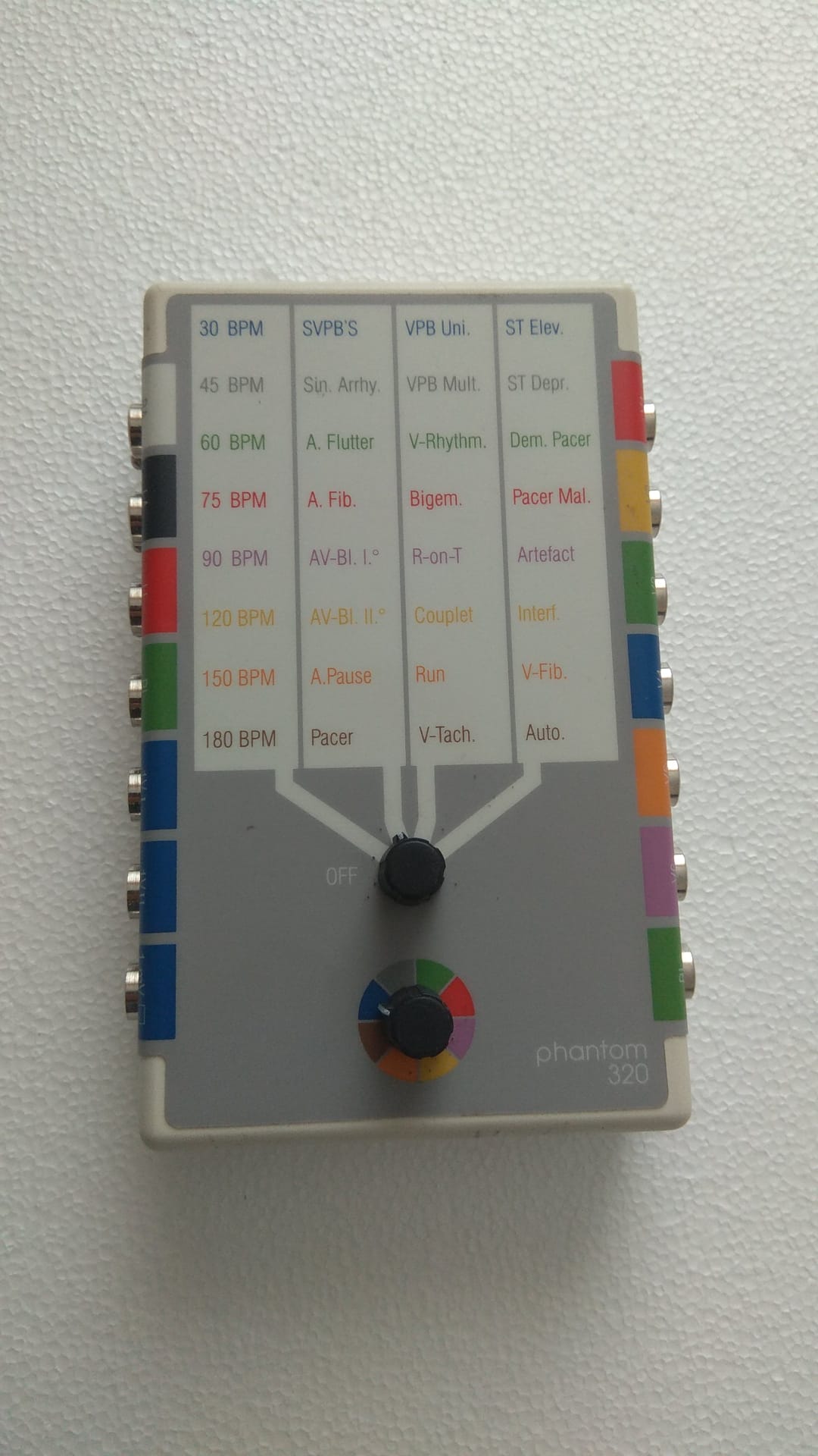
The device in the image is an ECG (Electrocardiogram) simulator used to test and calibrate ECG devices. The model name phantom 320 is clearly legible on the bottom right corner of the device’s front surface. No brand logo or name is otherwise specified.
General Status and Physical Condition
The general condition of the device appears to be good. No significant fractures, cracks, or deep dents have been detected on its plastic casing. The text and color-coded markings on the front panel are legible. There is slight dust and superficial usage-related contamination on the surface of the device. Two rotary knobs (potentiometers), which can be considered mechanical components, appear to be in place and intact. The markings surrounding these knobs are clear.
Technical Specifications and Control Panel
The front panel of the device features a matrix structure used to select different ECG rhythms and parameters. This structure is organized under four main columns:
- First Column (BPM): Contains values for 30, 45, 60, 75, 90, 120, 150, 180 BPM (Beats Per Minute).
- Second Column (Arrhythmias): Lists rhythm disorders and conditions such as SVPB’S, Sin. Arrhy., A. Flutter, A. Fib., AV-Bl. I°, AV-Bl. II°, A.Pause, and Pacer.
- Third Column (Ventricular Rhythms): Contains ventricular-originated rhythms such as VPB Uni., VPB Mult., V-Rhythm., Bigem., R-on-T, Couplet, Run, and V-Tach.
- Fourth Column (ST and Others): Includes ST segment changes, pacer conditions, and artifact options such as ST Elev., ST Depr., Dem. Pacer, Pacer Mal., Artefact, Interf., V-Fib., and Auto.
The upper rotary knob is used to select the columns on this matrix and includes an “OFF” position. The lower rotary knob allows for selection on a color-coded circular scale. These color codes correspond to the colors of the connection sockets on the sides of the device.
Connection Sockets and Accessories
There are metal socket inputs for connecting ECG cables on both the right and left sides of the device. Colored strips are located next to these sockets. On the left side, black, red, green, brown, and blue strips and sockets are visible. On the right side, red, yellow, green, blue, purple, and green strips and sockets are present. A total of 11 socket inputs have been counted. The image does not include the device’s box, connection cables, battery, or any documentation (invoice, warranty certificate, etc.). The device is displayed alone.
Label Information and Production Year
There is no label information regarding the serial number, lot number, REF code, or production year on the front surface of the device. This information is likely located on the back of the device or in the battery compartment, but it could not be determined from the image.
Usage Areas and Compatibility
This device is used by biomedical technical services, hospital biomedical departments, and ECG device manufacturers. It is utilized to test whether ECG devices, patient monitors, and the ECG modules of defibrillators are functioning correctly and whether they accurately detect different rhythms. The device is compatible with standard ECG patient cables.
Fault and Risk Assessment
There is no clear evidence of the device being faulty, such as broken parts, burn marks, or physical damage, in the images. The physical condition of the device is good. Since no significant wear, corrosion, or cable damage was observed, the potential risk of failure appears to be low. However, whether the electronic functions of the device are operational cannot be determined through visual analysis.